Arduinio Anemometer & Windvane
Interesting Anemometer Videos
What is an Anemometer and Wind Vane
An Anemometer is a weather sensor device used to measure wind speed. From Wikipedia, an anemometer is a device used for measuring the speed of wind, and is also a common weather station instrument. The term is derived from the Greek word anemos, which means wind, and is used to describe any wind speed measurement instrument used in meteorology. A weather vane, wind vane, or weathercock is an instrument for showing the direction of the wind. It is typically used as an architectural ornament to the highest point of a building. The word vane comes from the Old English word fana meaning "flag".
Wiring the Anemometer / WindVane to the Arduino Uno
One of the best sites that I visited that showed how to hook up the Davis Anemometer / Windvane was at cactus.io in Australia. I used their approach to wire up my sensor to the Arduino Uno/Ethernet Shield.
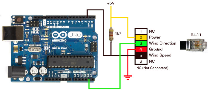
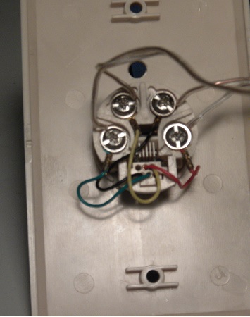
The anemometer/windvane has an RJ-11 jack on it, similar to a telephone jack. Fortunately, I had some spare telephone wall plates that I used to wire up to the Arduino, saving the trouble of cutting the wire. The overall wiring looks as follows:
The colors of the wires on the anemometer jack were different than what was shown in the above illustration. So I had to map the colors of the RJ-11 plug on the sensor cable to the wall plate colors as follows:
RJ-11 Plug Color |
Wire |
Wall Plate Wire Color |
|---|---|---|
Yellow |
Power |
Black |
Blue |
Wind Direction |
Red |
Red |
Ground |
Green |
Black |
Wind Speed |
Yellow |
As you noticed in the above Arduino wiring diagram, there are two connections to the Arduino. The Wind speed circuit is connected to a digital pin (digital Pin 2) and the wind direction circuit is connected to an analog pin (Analog Pin 4).
The wind speed circuit is a switch that is activated once per revolution of the wind cups. In this hookup, we are using a 4.7K pullup resistor. This will pull the pin 2 to 5V when the switch is open. If we don't use a pullup resistor, the circuit voltage could float and cause false triggers on the input. When the mercury switch on the wind cups close, pin 2 will be pulled to GND for a short duration while the magnet passes the switch. We use this pulse on pin 2 of the Arduino to detect every time the wind cups goes through one revolution. I'll discuss later how to measure the wind speed. For now, let's start with detecting the wind direction.
The Davis wind vane has a 20k linear potentiometer attached to it. The output from the wind direction circuit is connected to an analog pin on the Arduino. As we move the wind vane around we should get a reading between 0 and 1023. The Arduino has a 10 bit A to D converter which gives us the range of 0 to 1023. This would also correspond to a voltage of 0 to 5V. In the software, we will need to convert the 0 to 1023 to a 0 to 360 range to give us the wind direction.
The potentiometer in the wind vane has a dead band that will result in the value 0 on the analog pin. The diagram below shows the dead band for the Davis anemometer/windvane I'm using for testing. In this image we are looking down over the top of the wind vane. The anemometer is resting on the cups.
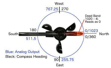
The wind vane is calibrated from the factory to be 0 when the vane is lined up along the length of the support bar pointing away from the mounting bracket.
Typically speaking, there are 8 compass points between 0° and 359°. These 8 compass points fall within a range of 45°. Below is a table showing how I set up the 8 compass points and the angular range I used:
Compass Point |
Angular Range |
North (N) |
337.5° to 22.5° |
NorthEast (NE) |
22.5° to 67.5° |
East (E) |
67.5° to 112.5° |
SouthWest (SE) |
112.5° to 157.5° |
South (S) |
157.5° to 202.5° |
SouthWest (SW) |
202.5° to 247.5° |
West (W) |
247.5° to 292.5° |
NorthWest (NW) |
292.5° to 337.5° |
In my Arduino Sketch, I use this to give me not only the wind direction in degrees but also the compass point direction.
This could easily be increased to 16 compass points if you want to include NNE, SSW, WNW, etc, if you wanted to do that. But keep in mind that means more code in the Arduino sketch.
The simplest way to set up the anemometer for wind direction calibration is to have the mounting arm pointing directly to north on the compass. This means the direction that is obtained by converting the analog input value to a direction value will line up correctly with North. However if you are unable to point the mounting arm to magnetic north then we need to apply an offset to our wind direction calculation to correct the wind direction reading.
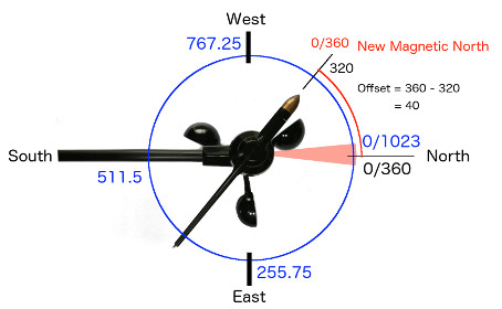
To determine the offset to apply we need to point the wind vane to magnetic north. Using a compass we can determine the angle offset from the wind vane to the support bar. The 0 to 1023 output value from the wind vane stays relative the metal support bar. We then translate the 0 - 1023 value to a 0 - 360 value it is still relative to the support bar. However our magnetic north heading is now 40 degrees to the left of the support bar.
In the situation in the diagram above we need to add 40 to the translated wind direction so that our direction reading is now showing the calibrated wind direction. In the sketch we now need to supply the offset value. To do this change the value on line 5 to #define Offset 40. In the situation below we need to subtract -45 from the wind direction. We need to set the offset on line 5 to #define Offset -45.
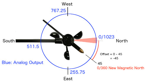
If the magnetic north heading relative to the support bar is between 0 to 180 then we subtract the offset from the Direction output to get the adjusted wind direction. If the magnetic north heading relative to the support bar is between 181 to 360 then we add the offset to the Direction output to get the adjusted wind direction.
This is not the only way to calibrate the wind direction but it works for the way we calculate wind direction in the software.
The Arduino Wind Direction Sketch
The following Arduino sketch reads the values on the Analog input pin. converts the raw A/D to a compass value and then displays the direction.
Davis Wind Direction Sketch (Download Sketch) |
	// Arduino sketch to display wind direction using a Davis Anemometer / Wind Vane

	int VaneValue;      // raw analog value from wind vane
	int Direction;  slated 0 - 360 direction
	int CalDirection;   // converted value with offset applied
	int LastValue;      // last direction value

	#define Offset 0;

	void setup()
	{
	LastValue = 0;
	Serial.begin(9600);
	Serial.println("Vane Value\tDirection\tHeading");
	}

	void loop()
	{
	delay(1000);                                    // wait for a second
	VaneValue = analogRead(A4);                     // Read the analog value from the A/D converter
	Direction = map(VaneValue, 0, 1023, 0, 359);    // Map the A/D value into the compass range
	CalDirection = Direction + Offset;              // Add an offset if the anemometer/windvane arm is not pointing North

	if(CalDirection > 360)                          // Calculate for a calibrated anemometer/windvane arm
	CalDirection = CalDirection - 360;

	if(CalDirection < 0)
	CalDirection = CalDirection + 360;

	// Only update the display if change greater than 2 degrees. Otherwise skip until a change is detected.
	if(abs(CalDirection - LastValue) > 2)
	{
	Serial.print(VaneValue); Serial.print("\t\t");
	Serial.print(CalDirection); Serial.print("\t\t");
	getHeading(CalDirection);                     // Get the compass heading to display
	LastValue = CalDirection;                     // Set the LastValue variable to dtermine of direct changed > 2 degrees
	}
	}

	// Converts compass direction to heading
	void getHeading(int direction) {
	if(direction > 337 and direction <= 22)
	Serial.println("N");
	else if (direction > 22 and direction <= 67)
	Serial.println("NE");
	else if (direction > 67 and direction <= 112)
	Serial.println("E");
	else if (direction > 112 and direction <= 157)
	Serial.println("SE");
	else if (direction > 157 and direction <= 202)
	Serial.println("S");
	else if (direction > 202 and direction <= 247)
	Serial.println("SW");
	else if (direction > 247 and direction <= 292)
	Serial.println("W");
	else if (direction > 292 and direction <= 337)
	Serial.println("NW");
	else
	Serial.println("N");
	}
|
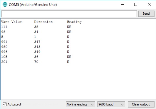
The output in the Arduino serial monitor should look like the following:
How to measure wind speed with the Anemometer
The wind cups of the anemometer assembly have a reed switch mounted inside near the shaft. This switch is activated once per revolution of the cups. To calculate the wind speed, a formula must be used to convert the number of times the switch activates per period of time to miles per hour.
According to the Davis Anemometer technical document that came with my weather station, 1 mile per hour is equal to 1600 revolutions per hour.
Using the formula V = P(2.25/T) we can calculate the speed in miles per hour, where:
==> V is speed in miles per hour
==> P is number of pulses per sample period (same as Wind Speed Sample Period on the data sheet)
==> T is the sample period in seconds
In the Arduino sketch, we are using the formula as provided by Davis to calculate the instantaneous wind speed in miles per hour.
Due to the random nature of switch activations on pin 2 (sometimes referred to switch bounce), a hardware interrupt on digital input pin 2 is used, which generates an interrupt on the falling edge of the pulse (5V dropping to ground and back to 5V when the switch is closed by the anemometer). The interrupt service routine (ISR) that is executed on the interrupt increments a counter.
Since the Davis spec states that the wind speed sample period is 2.25 seconds, it's safe to use a delay of 3 seconds to get an average sample for the wind speed. Even though the delay will halt the loop code for that period of time, the interrupt handler called "Rotation" is still executed. This will be the sample period (T) used in the calculation. The calculation is performed in the main loop.
Note: Code in Interrupt Service Routines should be kept to a minimum.
| Davis Wind Speed Sketch 1 Download Sketch |
// Arduino sketch to display wind speed using a Davis Anemometer / Wind Vane #include |
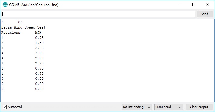
The output should look like the following:
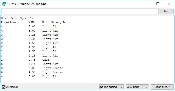
If you want to add more flare to the output, you can use the windspeed to determine a particular wind strength string that will related to the wind speed. For example, in the next sketch, I added a wind strength function using the following criteria (source: Wikipedia):
Wind Speed (MPH) |
Wind Speed (Knots) |
Wind Strength |
Beaufort Number |
| <1 MPH | <1 knot | Calm | 0 |
| 1 - 3 MPH | 1 - 3 knots | Light Air | 1 |
| 4 - 7 MPH | 4 - 6 knots | Light Breeze | 2 |
| 8 - 12 MPH | 7 - 10 knots | Gentle Breeze | 3 |
| 13 - 18 MPH | 11 - 16 knots | Moderate Breeze | 4 |
| 19 - 24 MPH | 17 - 21 knots | Fresh Breeze | 5 |
| 25 - 31 MPH | 22 - 27 knots | Strong Breeze | 6 |
| 32 - 38 MPH | 28 - 33 knots | Near Gale | 7 |
| 39 - 46 MPH | 34 - 40 knots | Gale | 8 |
| 47 - 54 MPH | 41 - 47 knots | Strong Gale | 9 |
| 55 - 63 MPH | 48 - 55 knots | Storm | 10 |
| 64 - 72 MPH | 56 - 63 knots | Violent Storm | 11 |
| >72 MPH | >63 knots | Hurricane Force | 12 |
| Davis Wind Speed Sketch 2 (Download Sketch) |
// Arduino sketch to display wind speed using a Davis Anemometer / Wind Vane #include |
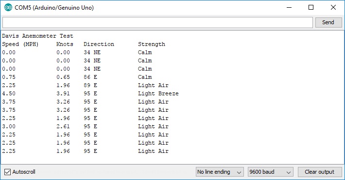
The output should look like the following:
This should give you enough information to use the David Anemometer / Wind Vane
The Arduino Wind Speed and Direction Sketch
Finally, I took some of the code used on the wind direction and wind speed sketch to create a combined program that does both. Using basic math, you can also display the wind speed in knots or km/hr. We can also display the window direction by degrees or direction based on the wind vane position.
In this revised sketch, I will use a timer interrupt that will generate an interrupt when the 0.5 second timer is triggered. The interrupt service routine called "isr_timer" will execute and this will be used to create a 2.5 second sample period.
I used the TimerOne library to provide the timer interrupt functionality. You can download this library from several sources including the arduino website.
Make sure that the variables WindSensorPin (line 2), WindVanePin (line 3) and VaneOffset (line 4) match your configuration.
| Davis Wind Speed / Direction Sketch (Download Sketch) |
// Arduino sketch to display both Wind Speed and Direction #include "TimerOne.h" // Timer Interrupt set to 2 second for read sensors #include |
The output should look like the following: